Saturday, October 19, 2013

Introduction

Although a far greater percentage of the electrical machines in service are a.c. machines, the d.c. machines are of considerable industrial importance. The principal advantage of the d.c. machine, particularly the d.c. motor, is that it provides a fine control of speed. Such an advantage is not claimed by any a.c.
motor. However, d.c. generators are not as common as they used to be, because direct current, when required, is mainly obtained from an a.c. supply by the use of rectifiers. Nevertheless, an understanding of d.c. generator is important because it represents a logical introduction to the behaviour of d.c. motors.
Indeed many d.c. motors in industry actually operate as d.c. generators for a brief period. In this UNIT, we shall deal with various aspects of d.c. generators.

Friday, October 18, 2013

 D.C. Motor Characteristics

There are three principal types of d.c. motors viz., shunt motors, series motors
and compound motors. Both shunt and series types have only one field winding
wound on the core of each pole of the motor. The compound type has two
separate field windings wound on the core of each pole. The performance of a
d.c. motor can be judged from its characteristic curves known as motor
characteristics, following are the three important characteristics of a d.c. motor:

(i) Torque and Armature current characteristic (Ta/Ia)
It is the curve between armature torque Ta and armature current Ia of a d.c.
motor. It is also known as electrical characteristic of the motor.

(ii) Speed and armature current characteristic (N/ia)
It is the curve between speed N and armature current Ia of a d.c. motor. It is very important characteristic as it is often the deciding factor in the selection of the motor for a particular application.

(iii) Speed and torque characteristic (N/Ta)
It is the curve between speed N and armature torque Ta of a d.c. motor. It is also

known as mechanical characteristic.

LOSSES IN A DC MOTOR

Losses in a D.C. Motor

The losses occurring in a d.c. motor are the same as in a d.c. generator  
(i) copper losses
 (ii) Iron losses or magnetic losses 
(iii) mechanical losses 


These losses cause 
(a) an increase of machine temperature and 
(b) reduction in the efficiency of the d.c. motor.
The following points may be noted:
(i) Apart from armature Cu loss, field Cu loss and brush contact loss, Cu losses also occur in interpoles (commutating poles) and compensating windings. Since these windings carry armature current (Ia),
Loss in interpole winding = I2× Resistance of interpole winding.
Loss in compensating winding = I2× Resistance of compensating winding.

(ii) Since d.c. machines (generators or motors) are generally operated at constant flux density and constant speed, the iron losses are nearly constant.

(iii) The mechanical losses (i.e. friction and windage) vary as the cube of the speed of rotation of the d.c. machine (generator or motor). Since d.c. machines are generally operated at constant speed, mechanical losses are
considered to be constant.

COMMUTATION IN DC MOTOR

 Commutation in D.C. Motors

Since the armature of a motor is the same as that of a generator, the current from the supply line must divide and pass through the paths of the armature windings.

In order to produce unidirectional force (or torque) on the armature conductors of a motor, the conductors under any pole must carry the current in the same direction at all times. This is illustrated in Fig. In this case, the current flows away from the observer in the conductors under the N-pole and towards
the observer in the conductors under the S-pole. Therefore, when a conductor moves from the influence of N-pole to that of S-pole, the direction of current in the conductor must be reversed. This is termed as commutation. The function of the commutator and the brush gear in a d.c. motor is to cause the reversal of current in a conductor as it moves from one side of a brush to the other. For
good commutation, the following points may be noted:

(i) If a motor does not have commutating poles (compoles), the brushes must be given a negative lead i.e., they must be shifted from G.N.A. against the direction of rotation of, the motor.

(ii) By using interpoles, a d.c. motor can be operated with fixed brush positions for all conditions of load. For a d.c. motor, the commutating poles must have the same polarity as the main poles directly back of them. This is the opposite of the corresponding relation in a d.c. generator.

Note. A d.c. machine may be used as a motor or a generator without changing the commutating poles connections. When the operation of a d.c. machine changes from generator to motor, the direction of the armature current reverses.
Since commutating poles winding carries armature current, the polarity of  commutating pole reverses automatically to the correct polarity.


ARMATURE REACTION IN DC MOTOR

Armature Reaction in D.C. Motors

As in a d.c. generator, armature reaction also occurs in a d.c. motor. This is expected because when current flows through the armature conductors of a d.c. motor, it produces flux (armature flux) which lets on the flux produced by the main poles. For a motor with the same polarity and direction of rotation as is for generator, the direction of armature reaction field is reversed.

(i) In a generator, the armature current flows in the direction of the induced e.m.f. (i.e. generated e.m.f. Eg) whereas in a motor, the armature current flows against the induced e.m.f. (i.e. back e.m.f. Eg). Therefore, it should be expected that for the same direction of rotation and field polarity, the armature flux of the motor will be in the opposite direction to that of the generator. Hence instead of the main flux being distorted in the direction of rotation as in a generator, it is distorted opposite to the direction of rotation. We can conclude that:
Armature reaction in a d.c. generator weakens the jinx at leading pole tips and strengthens the flux at trailing pole tips while the armature reaction in a d. c. motor produces the opposite effect.

(ii) In case of a d.c. generator, with brushes along G.N.A. and no commutating poles used, the brushes must be shifted in the direction of rotation (forward lead) for satisfactory commutation. However, in case of a d.c. motor, the brushes are given a negative lead i.e., they are shifted against the direction of rotation.
With no commutating poles used, the brushes are given a forward lead in a d.c. generator and backward lead in a d.c. motor.

(iii) By using commutating poles (compoles), a d.c. machine can be operated with fixed brush positions for all conditions of load. Since commutating poles windings carry the armature current, then, when a machine changes from generator to motor (with consequent reversal of current), the polarities of commutating poles must be of opposite sign.
Therefore, in a d.c. motor, the commutating poles must have the same polarity as the main poles directly back of them. This is the opposite of the corresponding relation in a d.c. generator.

Torque and Speed of a D.C. Motor

For any motor, the torque and speed are very important factors. When the torque increases, the speed of a motor increases and vice-versa. We have seen that for a d.c. motor;
N = K (V- IaRa)/ Ф = K Eb/ Ф…………………………………………….(i)
Tα ФIa…………………………………………………………………………(ii)
If the flux decreases, from Eq.(i), the motor speed increases but from Eq.(ii) the motor torque decreases. This is not possible because the increase in motor speed must be the result of increased torque. Indeed, it is so in this case. When the flux decreases slightly, the armature current increases to a large value. As a result, in spite of the weakened field, the torque is momentarily increased to a high value and will exceed considerably the value corresponding to the load. The surplus torque available causes the motor to accelerate and back e.m.f  (Ea=PФZN/60A) to rise. Steady conditions of speed will ultimately be achieved when back e.m.f. has risen to such a value that armature current[Ia = (V- Ea)/ Ra]develops torque just sufficient to drive the load.

Illustration
Let us illustrate the above point with a numerical example. Suppose a 400 V
shunt motor is running at 600 r.p.m., taking an armature current of 50 A. The armature resistance is 0.28 Ω. Let us see the effect of sudden reduction of flux by 5% on the motor.
Initially (prior to weakening of field), we have,
Ea = V-IaRa= 400 – 50 × 0.28 = 386 volts
We know that Eb α Ф N. If the flux is reduced suddenly, Eb α Ф because inertia
of heavy armature prevents any rapid change in speed. It follows that when the flux is reduced by 5%, the generated e.m.f. must follow suit. Thus at the instant of reduction of flux, E’b = 0.95 × 386 = 366.7 volts.
Instantaneous armature current is
I’a=(V- E’b)/ R=(400-366.7)/0.28=118.9A
Note that a sudden reduction of 5% in the flux has caused the armature current to increase about 2.5 times the initial value. This will result in the production of high value of torque. However, soon the steady conditions will prevail. This will depend on the system inertia; the more rapidly the motor can alter the speed, the sooner the e.m.f. rises and the armature current falls.

SPEED OF A D.C. MOTOR

Speed of a D.C. Motor

Eb = V-IaRa
But Eb=PФZN/60A
PФZN/60A  = V- IaRa
Or  N = (V- IaRa)/ Ф ×  60A/ PZ
Or N = K (V- IaRa)/ Ф
But         V- IaRa = Ea
Therefore N= K Eb/ Ф
Or N α Eb/ Ф
Therefore, in a d.c. motor, speed is directly proportional to back e.m.f. Eand inversely proportional to flux per pole Ф.

Speed Relations
If a d.c. motor has initial values of speed, flux per pole and back e.m.f. as N1 ,Ф1 and Eb1 respectively and the corresponding final values are N2 ,Фand Eb2 then,
Nα Eb1/ Фand Nα Eb2/ Ф2
Therefore N2/ N1 = (Eb2/ Eb1) ×( Ф/ Ф2)
(i) For a shunt motor, flux practically remains constant so that Ф1 = Ф2.
therefore  N2/ N1 = Eb2/ Eb1
(ii) For a series motor, Ф α Ia prior to saturation.
therefore N2/ N1 = (Eb2/ Eb1) × (Ia1/Ia2)
where Ia1 = initial armature current
Ia2 = final armature current
Speed Regulation

The speed regulation of a motor is the change in speed from full-load to no-load and is expressed as a percentage of the speed at full-load i.e.
% Speed regulation = [( N.L. speed - F.L.speed)/F.L.speed ] × 100
=[(N-N)/N] × 100


where No = No – load .speed
N = Full – load speed

SHAFT TORQUE

Shaft Torque (Tsh)

The torque which is available at the motor shaft for doing useful work is known as shaft torque. It is represented by Tsh. FIGURE illustrates the concept of shaft torque. The total or gross torque Ta developed in the armature of a motor is not available at the shaft because a part of it is lost in overcoming the iron and frictional losses in the motor. Therefore, shaft torque Tsh is somewhat less than the armature torque Ta. The difference Ta – Tsh is called lost torque.

T- Tsh =9.55 × iron and frictional losses/N
For example, if the iron and frictional losses in a motor are 1600 W and the
motor runs at 800 r.p.m., then,
T- Tsh =9.55 × 1600 /800 =19.1 N-m
As stated above, it is the shaft torque Tsh that produces the useful output. If the speed of the motor is N r.p.m., then,
Output in watts= 2πN Tsh/60
or Tsh =Output in watts /(2πN /60 ) N-m
or Tsh = 9.55 ×Output in watts /N     N-m
 Armature Torque of D.C. Motor

Torque is the turning moment of a force about an axis and is measured by the product of force (F) and radius (r) at right angle to which the force acts i.e.
D.C. Motors torque
T = F × r
In a d.c. motor, each conductor is acted upon by a circumferential force F at a distance r, the radius of the armature (Fig. 4.8). Therefore, each conductor exerts a torque, tending to rotate the armature. The sum of the torques due to all armature conductors is known as gross or armature torque (Ta).
Let in a d.c. motor

r = average radius of armature in m
l = effective length of each conductor in m
Z = total number of armature conductors
A = number of parallel paths
i = current in each conductor = Ia/A
B = average flux density in Wb/m2
Φ = flux per pole in Wb
P = number of poles
Force on each conductor, F = B i l newtons

Torque due to one conductor = F × r newton- metre
Total armature torque, Ta = Z F r newton-metre
= Z B i l r
Now i = Ia/A, B = Φ/a where a is the x-sectional area of flux path per pole at
radius r. Clearly, a = 2πr l /P.
T= Z × (Ф/a)×( Ia/A)×l×r
T= Z × (ФP/2πr l)×( Ia/A)×l×r = Z Ф IaP/(2πA) N-m
or T= 0.159Z Ф Ia(P/A) N-m……………………………………(i)
so Ta
Tα Ф Ia
Hence torque in a d.c. motor is directly proportional to flux per pole and
armature current.
(i) For a shunt motor, flux Φ is practically constant.
Tα  Ia
(ii) For a series motor, flux Φ is directly proportional to armature current Ia
provided magnetic saturation does not take place.
Tα Ia2
up to magnetic saturation
Alternative expression for Ta
E= PФZN/60A
(60×Eb) /N= PФZ/A
From Eq.(i), we get the expression of Ta as:
T=0.159×(60× Eb/N)× Ia
T=9.55×( EbIa/N)
Note that developed torque or gross torque means armature torque Ta.

TYPES OF DC MOTOR

Types of D.C. Motors

There are three types of d.c. motors characterized by the
connections of field winding in relation to the armature viz.:

(i) Shunt-wound motor in which the field winding is connected in parallel with the armature . The current through the shunt field
winding is not the same as the armature current. Shunt field windings are designed to produce the necessary m.m.f. by means of a relatively large number of turns of wire having high resistance. Therefore, shunt field current is relatively small compared with the armature current.

(ii) Series-wound motor in which the field winding is connected in series with the armature . Therefore, series field winding carries the armature current. Since the current passing through a series field winding is the same as the armature current, series field windings must be designed with much fewer turns than shunt field windings for the same m.m.f. Therefore, a series field winding has a relatively small number of turns of thick wire and, therefore, will possess a low resistance.


(iii) Compound-wound motor which has two field windings; one connected in parallel with the armature and the other in series with it. There are two types of compound motor connections.

When the shunt field winding is directly connected across the armature terminals , it is called short-shunt connection. 


When the shunt winding is so connected that it shunts the series combination of armature and series field , it is called long-shunt connection.


The compound machines (generators or motors) are always designed so that the flux produced by shunt field winding is considerably larger than the flux produced by the series field winding. Therefore, shunt field in compound machines is the basic dominant factor in the production of the magnetic field in
the machine.

VOLTAGE AND POWER EQUATION OF DC MOTOR

Voltage Equation of D.C. Motor


Let in a d.c. motor ,
V = applied voltage
Eb = back e.m.f.
Ra = armature resistance
Ia = armature current
Since back e.m.f. Eb acts in opposition to the applied voltage V, the net voltage across the armature circuit is V- Eb. The armature current Ia is given by;
Ia = (V – Eb)/ Ra
or V = Eb + IaRa ……………………………..(i)
This is known as voltage equation of the d.c. motor.

Power Equation
If Eq.(i) above is multiplied by Ia throughout, we get,
VIa = EbIa +I2aRa
VIa= electric power supplied to armature (armature input)
EbIa = power developed by armature (armature output)
I2aRa = electric power wasted in armature (armature Cu loss)
Thus out of the armature input, a small portion (about 5%) is wasted as a I2aRa and the remaining portion EbIa is converted into mechanical power within the armature.

Condition For Maximum Power
The mechanical power developed by the motor is Pm= EbIa
Now Pm=VIa -I2aRa
Since, V and Ra are fixed, power developed by the motor depends upon armature current. For maximum power, dPm/dIashould be zero.
dPm/dIa = V – 2IaRa
or IaRa = V/2
Now, V = Eb + IaRa =Eb + V/2
therefore Eb=  V/2
Hence mechanical power developed by the motor is maximum when back e.m.f. is equal to half the applied voltage.
Limitations
In practice, we never aim at achieving maximum power due to the following reasons:
(i) The armature current under this condition is very large—much excess of rated current of the machine.
(ii) Half of the input power is wasted in the armature circuit. In fact, if we take into account other losses (iron and mechanical), the efficiency will be well below 50%.

Thursday, October 17, 2013

BACK EMF AND ITS SIGNIFICANCE

Back or Counter E.M.F.

When the armature of a d.c. motor rotates under the influence of the driving torque, the armature conductors move through the magnetic field and hence e.m.f. is induced in them as in a generator The induced e.m.f. acts in opposite direction to the applied voltage V(Lenz’s law) and in known as back or counter e.m.f. Eb. The back e.m.f. Eb(= P f ZN/60 A) is always less than the applied voltage V, although this difference is small when the motor is running under normal conditions.


Consider a shunt wound motor as shown. When d.c. voltage V is applied across the motor terminals, the field magnets are excited and armature conductors are supplied with current. Therefore, driving
torque acts on the armature which begins to rotate. As the armature rotates, back e.m.f. Eb is induced which opposes the applied voltage V. The applied voltage V has to
force current through the armature against the back e.m.f. Eb. The electric work done in overcoming and causing the current to flow against Eb is converted into mechanical energy developed in the
armature. It follows, therefore, that energy conversion in a d.c. motor is only possible due to the production of back e.m.f. Eb.
Net voltage across armature circuit = V - Eb
If Ra is the armature circuit resistance, then,
 Ia = (V – Eb)/ Ra
Since V and Ra are usually fixed, the value of Eb will determine the current drawn by the motor. If the speed of the motor is high, then back e.m.f. Eb (= P fZN/60 A) is large and hence the motor will draw less armature current and viceversa.

Significance of Back E.M.F.

The presence of back e.m.f. makes the d.c. motor a self-regulating machine i.e., it makes the motor to draw as much armature current as is just sufficient to develop the torque required by the load.
Armature current,
 Ia = (V – Eb)/ Ra

(i) When the motor is running on no load, small torque is required to overcome the friction and windage losses. Therefore, the armature current Ia is small and the back e.m.f. is nearly equal to the applied voltage.
(ii) If the motor is suddenly loaded, the first effect is to cause the armature to slow down. Therefore, the speed at which the armature conductors move through the field is reduced and hence the back e.m.f. Eb falls. The decreased back e.m.f. allows a larger current to flow through the armature and larger current means increased driving torque. Thus, the driving torque increases as the motor slows down. The motor will stop slowing down when the armature current is just sufficient to produce the increased torque required by the load.
(iii) If the load on the motor is decreased, the driving torque is momentarily in excess of the requirement so that armature is accelerated. As the armature speed increases, the back e.m.f. Eb also increases and causes the armature current Ia to decrease. The motor will stop accelerating when the armature current is just sufficient to produce the reduced torque required by the load.
It follows, therefore, that back e.m.f. in a d.c. motor regulates the flow of armature current i.e., it automatically changes the armature current to meet the load requirement.

CONSTRUCTION OF DC MOTOR

Construction of d.c. motor

The d.c. generators and d.c. motors have the same general construction. In fact, when the machine is being assembled, the workmen usually do not know whether it is a d.c. generator or motor. Any d.c. generator can be run as a d.c. motor and vice-versa. All d.c. machines have five principal components viz.,
 (i) field system 
(ii) armature core 
(iii) armature winding
 (iv) commutator 
(v)brushes 


(i) Field system

The function of the field system is to produce uniform magnetic field within which the armature rotates. It consists of a number of salient poles (of course, even number) bolted to the inside of circular frame (generally called yoke). The yoke is usually made of solid cast steel whereas the pole pieces are composed of stacked laminations. Field coils are mounted on the poles and carry the d.c. exciting current. The field coils are connected in such a way that adjacent poles have opposite polarity.
The m.m.f. developed by the field coils produces a magnetic flux that passesthrough the pole pieces, the air gap, the armature and the frame .
Practical d.c. machines have air gaps ranging from 0.5 mm to 1.5 mm. Since armature and field systems are composed of materials that have high permeability, most of the m.m.f. of field coils is required to set up flux in the air gap. By reducing the length of air gap, we can reduce the size of field coils (i.e. number of turns).

(ii) Armature core

The armature core is keyed to the machine shaft and rotates between the field poles. It consists of slotted soft-iron laminations (about 0.4 to 0.6 mm thick) that are stacked to form a cylindrical core as shown in Fig . The laminations are individually coated with a thin insulating film so that they do not come in electrical contact with each other. The purpose of laminating the core is to reduce the eddy current loss. The laminations are slotted to accommodate and provide mechanical security to the armature winding and to give shorter air gap for the flux to cross between the pole face and the armature “teeth”.

(iii) Armature winding

The slots of the armature core hold insulated conductors that are connected in a suitable manner. This is known as armature winding. This is the winding in which “working” e.m.f. is induced. The armature conductors are connected in series-parallel; the conductors being connected in series so as to increase the voltage and in parallel paths so as to increase the current. The armature winding of a d.c. machine is a closed-circuit winding; the conductors being connected in a symmetrical manner forming a closed loop or series of closed loops.

(iv) Commutator

A commutator is a mechanical rectifier which converts the alternating voltage generated in the armature winding into direct voltage across the brushes. The commutator is made of copper segments insulated from each other by mica sheets and mounted on the shaft of the machine. The armature conductors are soldered to the commutator segments in a suitable manner to give rise to the armature winding. Depending upon the manner in which the armature conductors are connected to the commutator segments, there are two types of armature winding in a d.c. machine viz., (a) lap winding (b) wave winding.
Great care is taken in building the commutator because any eccentricity will cause the brushes to bounce, producing unacceptable sparking. The sparks may bum the brushes and overheat and carbonise the commutator.

(v) Brushes

The purpose of brushes is to ensure electrical connections between the rotating commutator and stationary external load circuit. The brushes are made of carbon and rest on the commutator. The brush pressure is adjusted by means of adjustable springs. If the brush pressure is very large, the friction produces heating of the commutator and the brushes. On the other hand, if it is too weak, the imperfect contact with the commutator may produce sparking.

Multipole machines have as many brushes as they have poles. For example, a 4-pole machine has 4 brushes. As we go round the commutator, the successive brushes have positive and negative polarities. Brushes having the same polarity are connected together so that we have two terminals viz., the +ve terminal and
the -ve terminal.


FOR BETTER UNDERSTANDING SEE THE ANIMATION 

DC MOTOR PRINCIPLE AND WORKING

 D.C. Motor Principle


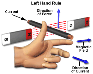
A machine that converts d.c. power into mechanical power is known as a d.c. motor. Its operation is based on the principle that when a current carrying conductor is placed in a magnetic field, the conductor experiences a mechanical force. The direction of this force is given by Fleming’s left hand rule and magnitude is given by; 
F = BIL newtons


Basically, there is no constructional difference between a d.c. motor and a d.c. generator. The same d.c. machine can be run as a generator or motor.

WORKING OF DC MOTOR


Consider a part of a multipolar d.c. motor. When the
terminals of the motor are connected to an external source of d.c. supply:
(i) the field magnets are excited developing alternate N and S poles;
(ii) the armature conductors carry ^currents. All conductors under N-pole carry currents in one direction while all the conductors under S-pole carry currents in the opposite direction.
Suppose the conductors under N-pole carry currents into the plane of the paper and those under S-pole carry currents out of the plane of the paper. Since each armature conductor is carrying current and is placed in the magnetic field, mechanical force acts on it.
Referring to figure and applying Fleming’s left hand rule, it is clear that force on each conductor is tending to rotate the armature in anticlockwise direction. All these forces add together to produce a driving torque which sets the armature rotating.
When the conductor moves from one side of a brush to the other, the current in that conductor is reversed and at the same time it comes under the influence of next pole which is of opposite polarity. Consequently, the direction of force on the conductor remains the same.

INTRODUCTION

Introduction

D. C. motors are seldom used in ordinary applications because all electric supply companies furnish alternating current However, for special applications such as in steel mills, mines and electric trains, it is advantageous to convert alternating current into direct current in order to use d.c. motors. The reason is that speed/torque characteristics of d.c. motors are much more superior to that of a.c. motors. Therefore, it is not surprising to note that for industrial drives, d.c. motors are as popular as 3-phase induction motors. Like d.c. generators, d.c. motors are also of three types viz., series-wound, shunt-wound and compound wound. The use of a particular motor depends upon the mechanical load it has to drive.

REMOVED AND REVOLVED SECTIONS

MACHINE PARTS

ISOMETRIC TO ORTHOGRAPHICS

ORTHOGRAPHIC PROJECTION 2

ORTHOGRAPHIC PROJECTION 1

ENGINEERING CURVES

DEVELOPMENT OF SURFACES IN DETAIL

DEVELOPMENT OF SURFACE

LOCI OF POINTS IN DETAILS

LOCI OF POINTS

PROJECTION OF SOLID

PROJECTION OF PLANES

PROJECTION OF STRAIGHT LINES

PROJECTION OF POINT AND LINES

PROJECTION OF POINTS

SCALE

ALL ABOUT DIMENSIONING

CLICK HERE All about Dimensioning

USING DRAWING TOOLS

CLICK HERE Using Drawing Tools

BASICS OF ENGINEERING GRAPHICS

Wednesday, October 16, 2013

GEOTHERMAL POWER PLANT

 WORKING AND LAYOUT


Working of geothermal plants

To harness the geothermal energy from geothermal areas, deep holes are drilled into the earth until a significant geothermal hot spot is found. It is very hard to build a geothermal power plant, so it need brilliant engineers. After discovering the hot spot we have to attach a pipe deep down inside the hole, which allows hot and high pressure steam to rise up to the Earthsurface. The power generation method is same as in other power plants, such as diesel power plant, nuclear power plant etc. This hot and high pressure steam is allowed to enter to the powerhouse situated at the Earthsurface.   

The power house consists of a high-speed steam turbine and a generator which is coupled to the steam turbine. Nothing more!. A condenser may be provided to condense the low pressure steam coming out of the turbine. It is essential to pump cold water to the hot spot through a separate pipe to make sure continuous steam output. If too much cold water is pumped to the hot spot inside the Earth, it could cool the rocks too much, resulting the geothermal source inactive.                                         

In simple, a geothermal power plant converts heat energy of the Earth to electricity by means of turbines, generators etc. In some geothermal areas, the geothermal water may not reaches the boiling point of water. In this situation, another fluid having lesser boiling points than water is incorporated with the steam-driven turbine system. When this fluid passes through the heat exchanger it causes the special fluid to flash to vapour which then drives the turbine.

FOR ANIMATION CLICK HERE

NUCLEAR POWER PLANT

Nuclear Power Plant,Types, Advantages and Disadvantages


Nuclear Power Plant


Nuclear power is generated using Uranium, which is a metal mined in various parts of the world.
The structure of a nuclear power plant in many aspects resembles to that of a conventional thermal power station, since in both cases the heat produced in the boiler (or reactor) is transported by some coolant and used to generate steam. The steam then goes to the blades of a turbine and by rotating it, the connected generator will produce electric energy. The steam goes to the condenser, where it condenses, i.e. becomes liquid again. The cooled down water afterwards gets back to the boiler or reactor, or in the case of PWRs to the steam generator.


The great difference between a conventional and a nuclear power plant is how heat is produced. In a fossile plant, oil, gas or coal is fired in the boiler, which means that the chemical energy of the fuel is converted into heat. In a nuclear power plant, however, energy that comes from fission reactions is utilized.
How it works


  • Nuclear power stations work in pretty much the same way as fossil fuel-burning stations, except that a "chain reaction" inside a nuclear reactor makes the heat instead.
  • The reactor uses Uranium rods as fuel, and the heat is generated by nuclear fission. Neutrons smash into the nucleus of the uranium atoms, which split roughly in half and release energy in the form of heat.
  • Carbon dioxide gas is pumped through the reactor to take the heat away, and the hot gas then heats water to make steam.
  • The steam drives turbines which drive generators. Modern nuclear power stations use the same type of turbines and generators as conventional power stations.
In Britain, nuclear power stations are built on the coast, and use sea water for cooling the steam ready
 to be pumped round again. This means that they don't have the huge "cooling towers" seen at other
 power stations.
The reactor is controlled with "control rods", made of boron, which absorb neutrons. When the rods are lowered into the reactor, they absorb more neutrons and the fission process slows down. To generate
 more power, the rods are raised and more neutrons can crash into uranium atoms.
Nuclear Power Plant TypesSeveral nuclear power plant (NPP) types are used for energy generation
 in the world. The different types are usually classified based on the main features of the reactor 
 applied in them. The most widespread power plant reactor types are: 
  • Light water reactors: both the moderator and coolant are light water (H2O). To this category belong the pressurized water reactors (PWR) and boiling water reactors (BWR).

  • Heavy water reactors (CANDU): both the coolant and moderator are heavy water (D2O).

  • Graphite moderated reactors: in this category there are gas cooled reactors (GCR) and light water cooled reactors (RBMK).

  • Exotic reactors (fast breeder reactors and other experimental installations).

  • New generation reactors: reactors of the future.
Advantages
  • Nuclear power costs about the same as coal, so it's not expensive to make.
  • The amount of fuel required is quite small ,therfore there is no problem of transportation, storage etc.
  • Does not produce smoke or carbon dioxide, so it does not contribute to the greenhouse effect.
  • Produces huge amounts of energy from small amounts of fuel.
  • Produces small amounts of waste.
  • The output control is most flexible.
  • Nuclear power is reliable.
Disadvantages

  • The fuel used is expensive and is difficult to recover.
  • The fission by-products are generally radio active and may cause a dangerous amount of radio active pollution.
  • Although not much waste is produced, it is very, very dangerous. It must be sealed up and buried for many years to allow the radioactivity to die away.
  • The initial capital cost is very high as compared to other power plants.
  • Nuclear power is reliable, but a lot of money has to be spent on safety - if it does go wrong, a nuclear accident can be a major disaster. People are increasingly concerned about this - in the 1990's nuclear power was the fastest-growing source of power in much of the world. In 2005 it was the second slowest-growing.
  • The cooling water requirements of a nuclear power plant are very heavy.
FOR NUCLEAR POWER PLANT ANIMATION CLICK HERE