Friday, October 18, 2013

SHAFT TORQUE

Shaft Torque (Tsh)

The torque which is available at the motor shaft for doing useful work is known as shaft torque. It is represented by Tsh. FIGURE illustrates the concept of shaft torque. The total or gross torque Ta developed in the armature of a motor is not available at the shaft because a part of it is lost in overcoming the iron and frictional losses in the motor. Therefore, shaft torque Tsh is somewhat less than the armature torque Ta. The difference Ta – Tsh is called lost torque.

T- Tsh =9.55 × iron and frictional losses/N
For example, if the iron and frictional losses in a motor are 1600 W and the
motor runs at 800 r.p.m., then,
T- Tsh =9.55 × 1600 /800 =19.1 N-m
As stated above, it is the shaft torque Tsh that produces the useful output. If the speed of the motor is N r.p.m., then,
Output in watts= 2πN Tsh/60
or Tsh =Output in watts /(2πN /60 ) N-m
or Tsh = 9.55 ×Output in watts /N     N-m
 Armature Torque of D.C. Motor

Torque is the turning moment of a force about an axis and is measured by the product of force (F) and radius (r) at right angle to which the force acts i.e.
D.C. Motors torque
T = F × r
In a d.c. motor, each conductor is acted upon by a circumferential force F at a distance r, the radius of the armature (Fig. 4.8). Therefore, each conductor exerts a torque, tending to rotate the armature. The sum of the torques due to all armature conductors is known as gross or armature torque (Ta).
Let in a d.c. motor

r = average radius of armature in m
l = effective length of each conductor in m
Z = total number of armature conductors
A = number of parallel paths
i = current in each conductor = Ia/A
B = average flux density in Wb/m2
Φ = flux per pole in Wb
P = number of poles
Force on each conductor, F = B i l newtons

Torque due to one conductor = F × r newton- metre
Total armature torque, Ta = Z F r newton-metre
= Z B i l r
Now i = Ia/A, B = Φ/a where a is the x-sectional area of flux path per pole at
radius r. Clearly, a = 2πr l /P.
T= Z × (Ф/a)×( Ia/A)×l×r
T= Z × (ФP/2πr l)×( Ia/A)×l×r = Z Ф IaP/(2πA) N-m
or T= 0.159Z Ф Ia(P/A) N-m……………………………………(i)
so Ta
Tα Ф Ia
Hence torque in a d.c. motor is directly proportional to flux per pole and
armature current.
(i) For a shunt motor, flux Φ is practically constant.
Tα  Ia
(ii) For a series motor, flux Φ is directly proportional to armature current Ia
provided magnetic saturation does not take place.
Tα Ia2
up to magnetic saturation
Alternative expression for Ta
E= PФZN/60A
(60×Eb) /N= PФZ/A
From Eq.(i), we get the expression of Ta as:
T=0.159×(60× Eb/N)× Ia
T=9.55×( EbIa/N)
Note that developed torque or gross torque means armature torque Ta.

TYPES OF DC MOTOR

Types of D.C. Motors

There are three types of d.c. motors characterized by the
connections of field winding in relation to the armature viz.:

(i) Shunt-wound motor in which the field winding is connected in parallel with the armature . The current through the shunt field
winding is not the same as the armature current. Shunt field windings are designed to produce the necessary m.m.f. by means of a relatively large number of turns of wire having high resistance. Therefore, shunt field current is relatively small compared with the armature current.

(ii) Series-wound motor in which the field winding is connected in series with the armature . Therefore, series field winding carries the armature current. Since the current passing through a series field winding is the same as the armature current, series field windings must be designed with much fewer turns than shunt field windings for the same m.m.f. Therefore, a series field winding has a relatively small number of turns of thick wire and, therefore, will possess a low resistance.


(iii) Compound-wound motor which has two field windings; one connected in parallel with the armature and the other in series with it. There are two types of compound motor connections.

When the shunt field winding is directly connected across the armature terminals , it is called short-shunt connection. 


When the shunt winding is so connected that it shunts the series combination of armature and series field , it is called long-shunt connection.


The compound machines (generators or motors) are always designed so that the flux produced by shunt field winding is considerably larger than the flux produced by the series field winding. Therefore, shunt field in compound machines is the basic dominant factor in the production of the magnetic field in
the machine.

VOLTAGE AND POWER EQUATION OF DC MOTOR

Voltage Equation of D.C. Motor


Let in a d.c. motor ,
V = applied voltage
Eb = back e.m.f.
Ra = armature resistance
Ia = armature current
Since back e.m.f. Eb acts in opposition to the applied voltage V, the net voltage across the armature circuit is V- Eb. The armature current Ia is given by;
Ia = (V – Eb)/ Ra
or V = Eb + IaRa ……………………………..(i)
This is known as voltage equation of the d.c. motor.

Power Equation
If Eq.(i) above is multiplied by Ia throughout, we get,
VIa = EbIa +I2aRa
VIa= electric power supplied to armature (armature input)
EbIa = power developed by armature (armature output)
I2aRa = electric power wasted in armature (armature Cu loss)
Thus out of the armature input, a small portion (about 5%) is wasted as a I2aRa and the remaining portion EbIa is converted into mechanical power within the armature.

Condition For Maximum Power
The mechanical power developed by the motor is Pm= EbIa
Now Pm=VIa -I2aRa
Since, V and Ra are fixed, power developed by the motor depends upon armature current. For maximum power, dPm/dIashould be zero.
dPm/dIa = V – 2IaRa
or IaRa = V/2
Now, V = Eb + IaRa =Eb + V/2
therefore Eb=  V/2
Hence mechanical power developed by the motor is maximum when back e.m.f. is equal to half the applied voltage.
Limitations
In practice, we never aim at achieving maximum power due to the following reasons:
(i) The armature current under this condition is very large—much excess of rated current of the machine.
(ii) Half of the input power is wasted in the armature circuit. In fact, if we take into account other losses (iron and mechanical), the efficiency will be well below 50%.

Thursday, October 17, 2013

BACK EMF AND ITS SIGNIFICANCE

Back or Counter E.M.F.

When the armature of a d.c. motor rotates under the influence of the driving torque, the armature conductors move through the magnetic field and hence e.m.f. is induced in them as in a generator The induced e.m.f. acts in opposite direction to the applied voltage V(Lenz’s law) and in known as back or counter e.m.f. Eb. The back e.m.f. Eb(= P f ZN/60 A) is always less than the applied voltage V, although this difference is small when the motor is running under normal conditions.


Consider a shunt wound motor as shown. When d.c. voltage V is applied across the motor terminals, the field magnets are excited and armature conductors are supplied with current. Therefore, driving
torque acts on the armature which begins to rotate. As the armature rotates, back e.m.f. Eb is induced which opposes the applied voltage V. The applied voltage V has to
force current through the armature against the back e.m.f. Eb. The electric work done in overcoming and causing the current to flow against Eb is converted into mechanical energy developed in the
armature. It follows, therefore, that energy conversion in a d.c. motor is only possible due to the production of back e.m.f. Eb.
Net voltage across armature circuit = V - Eb
If Ra is the armature circuit resistance, then,
 Ia = (V – Eb)/ Ra
Since V and Ra are usually fixed, the value of Eb will determine the current drawn by the motor. If the speed of the motor is high, then back e.m.f. Eb (= P fZN/60 A) is large and hence the motor will draw less armature current and viceversa.

Significance of Back E.M.F.

The presence of back e.m.f. makes the d.c. motor a self-regulating machine i.e., it makes the motor to draw as much armature current as is just sufficient to develop the torque required by the load.
Armature current,
 Ia = (V – Eb)/ Ra

(i) When the motor is running on no load, small torque is required to overcome the friction and windage losses. Therefore, the armature current Ia is small and the back e.m.f. is nearly equal to the applied voltage.
(ii) If the motor is suddenly loaded, the first effect is to cause the armature to slow down. Therefore, the speed at which the armature conductors move through the field is reduced and hence the back e.m.f. Eb falls. The decreased back e.m.f. allows a larger current to flow through the armature and larger current means increased driving torque. Thus, the driving torque increases as the motor slows down. The motor will stop slowing down when the armature current is just sufficient to produce the increased torque required by the load.
(iii) If the load on the motor is decreased, the driving torque is momentarily in excess of the requirement so that armature is accelerated. As the armature speed increases, the back e.m.f. Eb also increases and causes the armature current Ia to decrease. The motor will stop accelerating when the armature current is just sufficient to produce the reduced torque required by the load.
It follows, therefore, that back e.m.f. in a d.c. motor regulates the flow of armature current i.e., it automatically changes the armature current to meet the load requirement.

CONSTRUCTION OF DC MOTOR

Construction of d.c. motor

The d.c. generators and d.c. motors have the same general construction. In fact, when the machine is being assembled, the workmen usually do not know whether it is a d.c. generator or motor. Any d.c. generator can be run as a d.c. motor and vice-versa. All d.c. machines have five principal components viz.,
 (i) field system 
(ii) armature core 
(iii) armature winding
 (iv) commutator 
(v)brushes 


(i) Field system

The function of the field system is to produce uniform magnetic field within which the armature rotates. It consists of a number of salient poles (of course, even number) bolted to the inside of circular frame (generally called yoke). The yoke is usually made of solid cast steel whereas the pole pieces are composed of stacked laminations. Field coils are mounted on the poles and carry the d.c. exciting current. The field coils are connected in such a way that adjacent poles have opposite polarity.
The m.m.f. developed by the field coils produces a magnetic flux that passesthrough the pole pieces, the air gap, the armature and the frame .
Practical d.c. machines have air gaps ranging from 0.5 mm to 1.5 mm. Since armature and field systems are composed of materials that have high permeability, most of the m.m.f. of field coils is required to set up flux in the air gap. By reducing the length of air gap, we can reduce the size of field coils (i.e. number of turns).

(ii) Armature core

The armature core is keyed to the machine shaft and rotates between the field poles. It consists of slotted soft-iron laminations (about 0.4 to 0.6 mm thick) that are stacked to form a cylindrical core as shown in Fig . The laminations are individually coated with a thin insulating film so that they do not come in electrical contact with each other. The purpose of laminating the core is to reduce the eddy current loss. The laminations are slotted to accommodate and provide mechanical security to the armature winding and to give shorter air gap for the flux to cross between the pole face and the armature “teeth”.

(iii) Armature winding

The slots of the armature core hold insulated conductors that are connected in a suitable manner. This is known as armature winding. This is the winding in which “working” e.m.f. is induced. The armature conductors are connected in series-parallel; the conductors being connected in series so as to increase the voltage and in parallel paths so as to increase the current. The armature winding of a d.c. machine is a closed-circuit winding; the conductors being connected in a symmetrical manner forming a closed loop or series of closed loops.

(iv) Commutator

A commutator is a mechanical rectifier which converts the alternating voltage generated in the armature winding into direct voltage across the brushes. The commutator is made of copper segments insulated from each other by mica sheets and mounted on the shaft of the machine. The armature conductors are soldered to the commutator segments in a suitable manner to give rise to the armature winding. Depending upon the manner in which the armature conductors are connected to the commutator segments, there are two types of armature winding in a d.c. machine viz., (a) lap winding (b) wave winding.
Great care is taken in building the commutator because any eccentricity will cause the brushes to bounce, producing unacceptable sparking. The sparks may bum the brushes and overheat and carbonise the commutator.

(v) Brushes

The purpose of brushes is to ensure electrical connections between the rotating commutator and stationary external load circuit. The brushes are made of carbon and rest on the commutator. The brush pressure is adjusted by means of adjustable springs. If the brush pressure is very large, the friction produces heating of the commutator and the brushes. On the other hand, if it is too weak, the imperfect contact with the commutator may produce sparking.

Multipole machines have as many brushes as they have poles. For example, a 4-pole machine has 4 brushes. As we go round the commutator, the successive brushes have positive and negative polarities. Brushes having the same polarity are connected together so that we have two terminals viz., the +ve terminal and
the -ve terminal.


FOR BETTER UNDERSTANDING SEE THE ANIMATION 

DC MOTOR PRINCIPLE AND WORKING

 D.C. Motor Principle


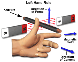
A machine that converts d.c. power into mechanical power is known as a d.c. motor. Its operation is based on the principle that when a current carrying conductor is placed in a magnetic field, the conductor experiences a mechanical force. The direction of this force is given by Fleming’s left hand rule and magnitude is given by; 
F = BIL newtons


Basically, there is no constructional difference between a d.c. motor and a d.c. generator. The same d.c. machine can be run as a generator or motor.

WORKING OF DC MOTOR


Consider a part of a multipolar d.c. motor. When the
terminals of the motor are connected to an external source of d.c. supply:
(i) the field magnets are excited developing alternate N and S poles;
(ii) the armature conductors carry ^currents. All conductors under N-pole carry currents in one direction while all the conductors under S-pole carry currents in the opposite direction.
Suppose the conductors under N-pole carry currents into the plane of the paper and those under S-pole carry currents out of the plane of the paper. Since each armature conductor is carrying current and is placed in the magnetic field, mechanical force acts on it.
Referring to figure and applying Fleming’s left hand rule, it is clear that force on each conductor is tending to rotate the armature in anticlockwise direction. All these forces add together to produce a driving torque which sets the armature rotating.
When the conductor moves from one side of a brush to the other, the current in that conductor is reversed and at the same time it comes under the influence of next pole which is of opposite polarity. Consequently, the direction of force on the conductor remains the same.